SUPER FLUX LED Lighting the Future
special-lighting
SUPER FLUX LED

SUPER FLUX LED


Features:

High Luminance output.

Designed for High Current Operation.

Low Thermal Resistance.

Low Profile.

Packaged in Tubes for Use with Automatic Insertion Equipment .

RoHS Compliant.

UV resistant epoxy.

Applications
Automotive Lighting
Electronic Signs and Signals
Special Lighting Application
SUPER FLUX LED
SPECIFICATION (Ta = 25℃,@IF = 70 mA)
Model
(Emitting Color)
SF-RSHH
red
SF-RSEE
red
SF-YSHH
yellow
SF-YSEE
yellow
Power Dissipation 200 mW 200 mW
Peak Forward Current (Duty 1/10@1KHZ)* 160 mA 160 mA
Continuous Forward Current 70 mA 70 mA
Reverse Voltage 5 V 5 V
Operating Temperature Range -40~+80 ℃ -40~+80 ℃
Storage Temperature Range -40~+85 ℃ -40~+85 ℃
Lead Soldering Temperature 260 ℃ 260 ℃
Material AlInGaP AlInGaP
Lens water clear water clear
Forward Voltage 2~3 V 2~3 V
Luminous Intensity ±20 % 10,000~17,000 mcd 13,000~22,000 mcd 10,000~17,000 mcd 13,000~22,000 mcd
Dominant Wavelength 618~630 nm 585~596 nm
Typical Viewing Angle (2θ1/2) 45 23 45 23
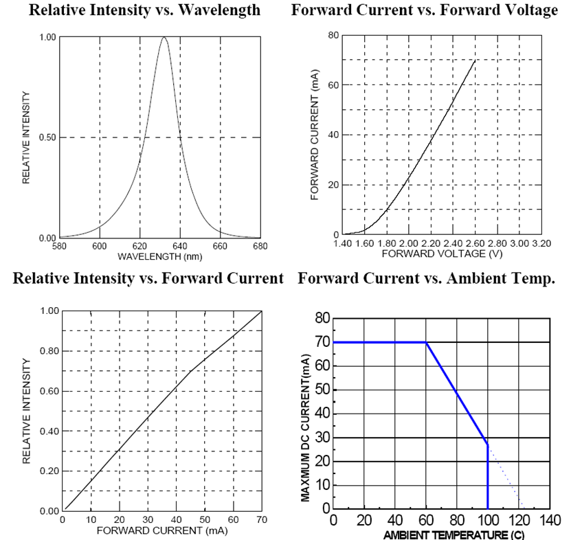
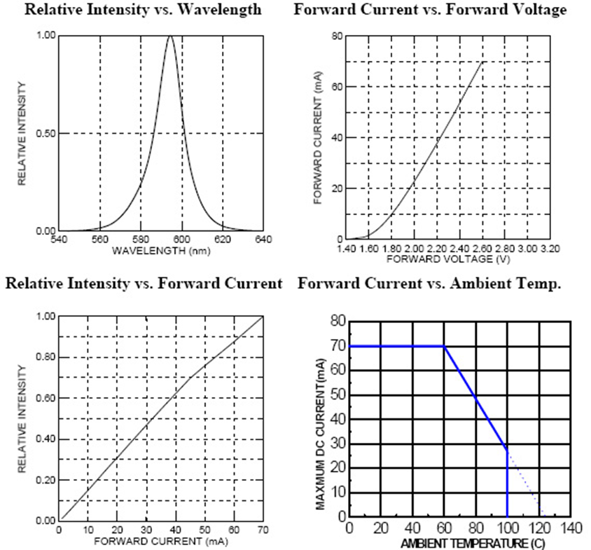
Typical Electro-Optical Characteristics Curves
red

amber

* Duty ratio max 1/10; Pulse Width max. 0.1 ms

At the position of 4 mm from the bottom of the package within 5 seconds.


Caution in ESD

  1. Static Electricity and surge damages the LEDs. It is recommended to use a wrist band or anti-electrostatic glove when handling the LEDs. All devices, Equipment and machinery must be properly grounded.
  2. When inspecting own final products on which LEDs were mounted, It is easy to find static-damaged LEDs by light emission test at lower current (below 1 mA is recommended).
  3. Damaged LEDs will show some unusual characteristics such as leak current remarkably increases, starting forward voltage becomes lower, or the LEDs get unlighted at the low current.

Notes

  1. Above specification may be changed without notice. SO BRIGHT will reserve authority on material change for above specification.
  2. When using this product, please observe the absolute maximum ratings and the instructions for using outlined in these specification sheets. SO BRIGHT assumes no responsibility for any damage resulting from use of the product which does not comply with the absolute maximum ratings and the instructions included in these specification sheets.
  3. Soldering Condition: Careful attention should be paid during soldering. When soldering, leave more then 3 mm from solder joint to case, and soldering beyond the base of the tie bar is recommended. Avoiding applying any stress to the lead frame while the LEDs are at high temperature particularly when soldering.

Recommended soldering conditions:

Hand Soldering DIP Soldering
Temo. at tip of iron 400 ℃ Max. (30 W Max.) Preheat temp. 100 ℃ Max. (60 sec Max.)
Soldering time 3 sec Max. Bath temp. 265 Max.
Distance 3 mm Min. (From solder joint to case) Bath time. 5 sec Max.
Distance 3 mm Min.